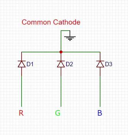
If your LEDs cathodes are connected to rows and anodes to columns, you may turn a particular LED in this matrix on by providing voltage to the appropriate column and ground to the appropriate row, while keeping the rest in their respective ‘off’ states. The basic multiplexing structure is a 2D matrix with all rows and columns connected to controlling sources.

‘Normal’ multiplexing deals with just two states of controlling pins (an active high/low and ‘the other’ one) and can turn on multiple LEDs at the same time.
USING COMMON CATHODE LED WITH COMMON ADONE OUTPUT DRIVERS
For now, let’s just note that Charlieplexing a) works with microcontrollers and not with shift registers or LED drivers and b) turns on only one LED at any given time. There are tons of Charlieplexing Instructables, you can read about its theory here. If you switch between the LEDs really fast, the persistence of vision will make them look like they’re all on. As the LEDs turn on only when they have voltage on the anode and ground on the cathode and do nothing in any other situation, it is possible to connect a lot of LEDs to a small number of microcontroller pins in all the physically possible ways and turn them on one by one, turning one pin high, one low, and keeping the rest in input mode. These pins can be active high, active low and passive (aka input, or high impedance state). These techniques are often mixed up, but, while their basic principle (persistence of vision) and their end result are relatively the same, the ways they achieve this result are fundamentally different, and it is important to understand the difference right from the start to avoid confusion later.Ĭharlieplexing relies on the tri-state nature of the microcontroller pins. There are two main techniques employed when multiplexing LEDs. There is a certain wow-factor, however, so some fun will be provided. With these two projects, I’m trying to help better understand the ways multiplexing, timers and interrupts work.

There are better ways to control multiple RGB LEDs off an Arduino. Please note that this Instructable is educational, not practical. 1 demux chip, either 74HC138 or 74HC238 3 or 8 MOSFETs, P-Channel or N-Channel respectfully 6 or 16 RGB LEDs, either common anode or common cathode So, to test the stuff explained here, you’ll need: It’s very easy to switch between the N- and P-Channel MOSFETs, provided you also use a different type of LEDs and demux chip I’ll give the details. But, alas, I have only three P-Channels MOSFETs in breadboard-friendly packages. In most cases, you should stick to the first pair while dealing with LEDs, as all the LED drivers are current-sinking devices. The first project will be common-anode LEDs and P-Channel MOSFETs, the second one will use common cathode LEDs and N-Channels. The first one drives 6 RGB LEDs using just three MOSFETs the second one drives 16 LEDs but needs eight MOSFETs and a demultiplexing chip. And to do this, I built a couple of devices that use the bare minimum of hardware between the Arduino and the RGB LEDs to make the clearest possible picture of how the multiplexing works.

There are a lot of Instructables dealing with multiplexing, but most of them describe the particular project and do not cover the basics I decided to amend that. Thanks for your reply, I tried 10K on the base of the red and green transistors but it made no difference whatsoever.There are multiple ways to light a lot of LEDs off an Arduino (or any other microcontroller): shift registers, LED drivers, programmable LEDs, but the more LEDs you want to control, the closer you’re getting to the multiplexing: the ultimate technique for driving hundreds and thousands of LEDs. I'm using an attiny85 8MHz (internal), the pwm config is as follows: pinMode(0, OUTPUT) I already tried to shunt the top and bottom power rails but makes no difference. This power supply is rated <700mA so with 6 leds I'm well inside the range.Ĭould this be be an implementation problem, or something caused by a cheap bread board ? I'm powering the bread board with a small bread board power supply from 12v. I didn't had this problem when driving only one led without the transistors.Īpart from the leds I do have a button with simple RC debouncing. The only snag is that rgb(0,0,0) (the 3 pwm attiny85 solution I'm using already inverts the pwm value) is not black, I have always some light on red and green (but not on blue). I implemented this circuit using 3 BC327-40 with 1k resistors to the base and it works ok, I'm driving 6 RGB leds without problem.


 0 kommentar(er)
